After several months work on both the hardware and software, I’ve finally released version 1.0 of the TRSpectrometer software. This is an open-source platform for time-resolved spectroscopy which I’ve now declared to be in a usable state, fit for public consumption.
The version 1.0 includes a reference hardware design for a transient absorption (pump–probe) spectrometer, along with a full GUI application for the acquisition of data.
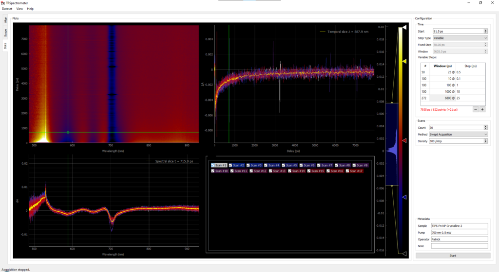
Raw data acquisition panel of the TRSpectrometer application.
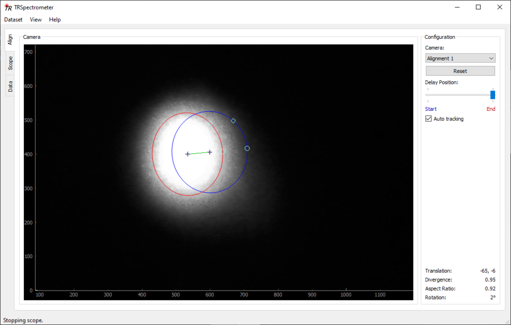
The software features a plugin architecture which allows for flexible additions and modifications to the application. This should make it easy to support different hardware types, experimental methods, or other tools for alignment or data analysis. For example, a plugin is included which uses a webcam and computer vision to assist with alignment of translating delay stages:
Alignment panel plugin for the TRSpectrometer application. A translating delay stage can be aligned with the help of a webcam and computer vision.
The application can be used for data acquisition, or simply for viewing and exploring data. A set of “dummy” hardware devices are configured by default so users can immediately test out some of the acquisition features.
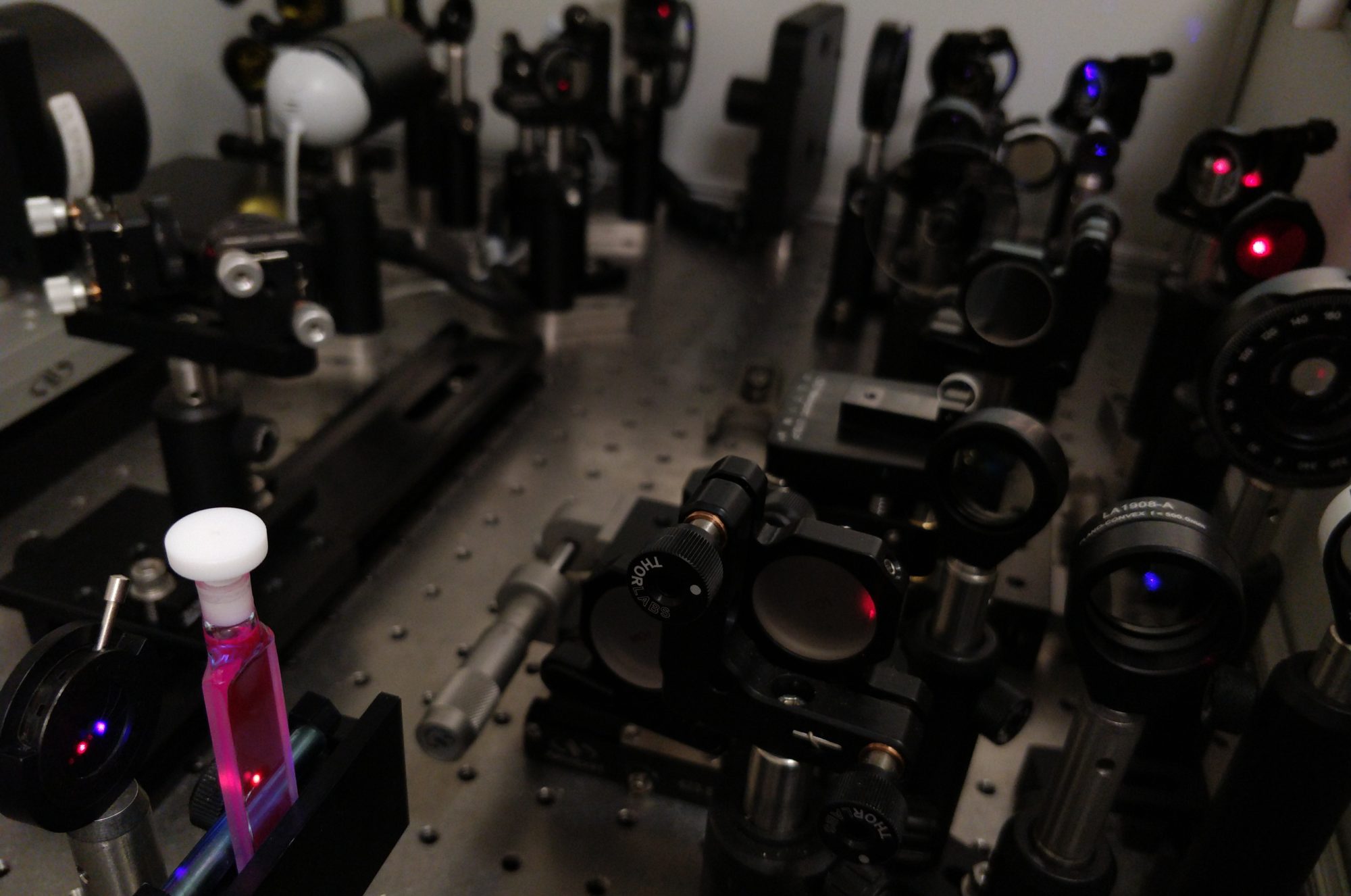
Our Millennia Prime stopped working, tripping the circuit breakers. I’m hoping it’s just power supply issues, and it’s out of warranty, so let’s take a look. Just don’t think about how much this thing costs…
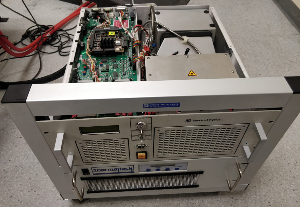
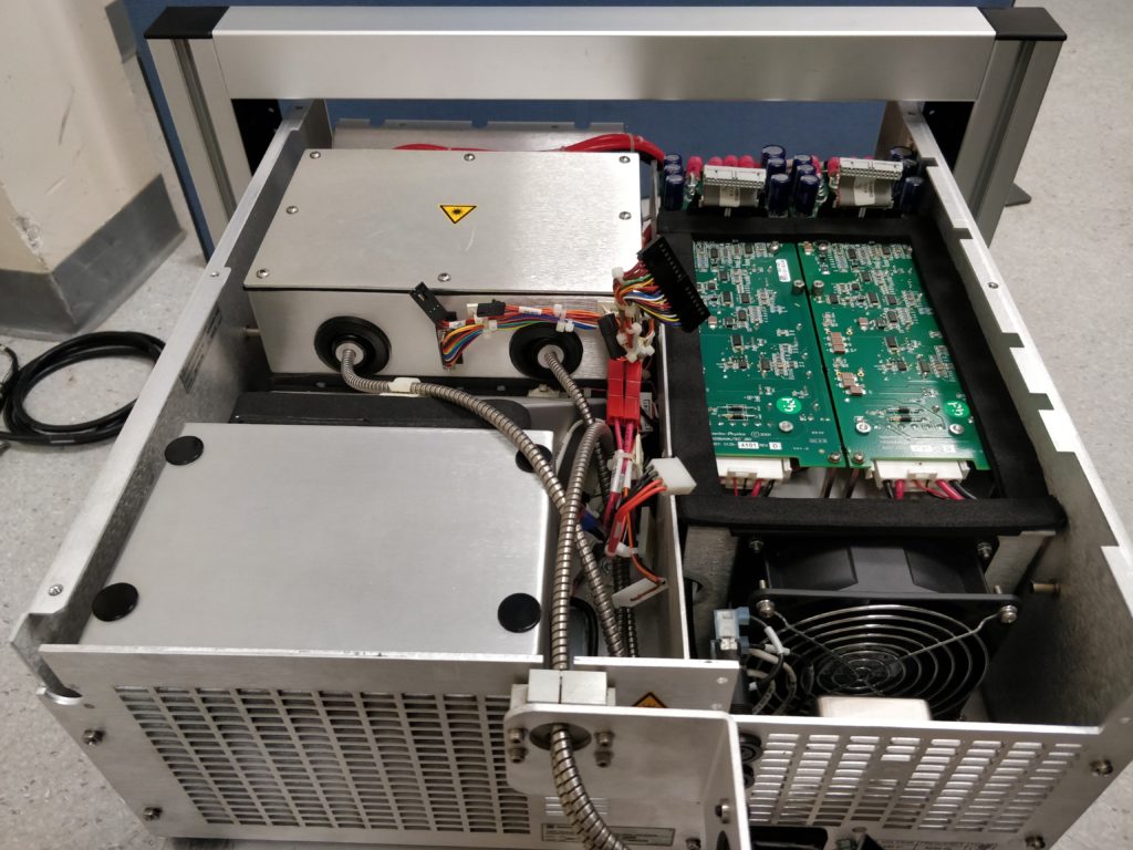
The Spectra-Physics J80 laser diode pump for the Millennia Prime unit, minus top panel.
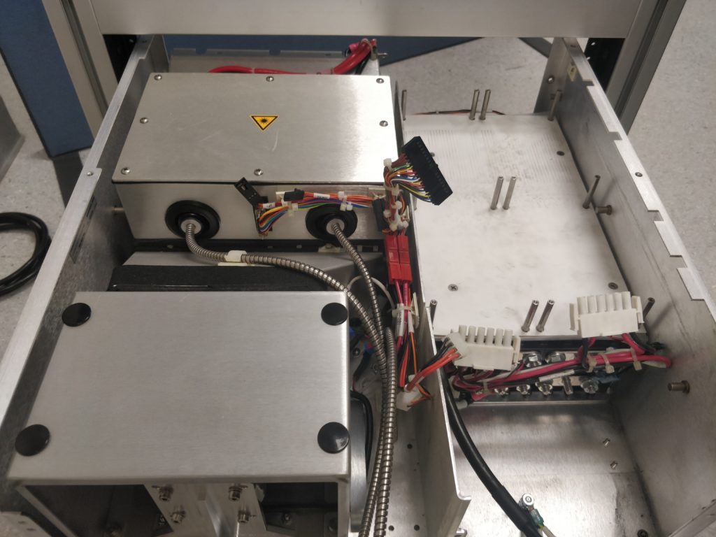
Getting to the power supply unit doesn’t look like fun… It is mounted on the bottom left, underneath a couple of layers of circuitry. At this point it’s impossible to even see what sort of unit it is.
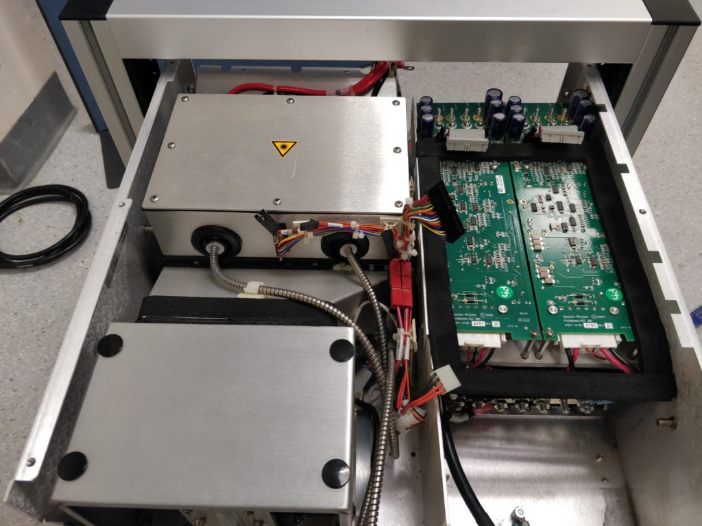
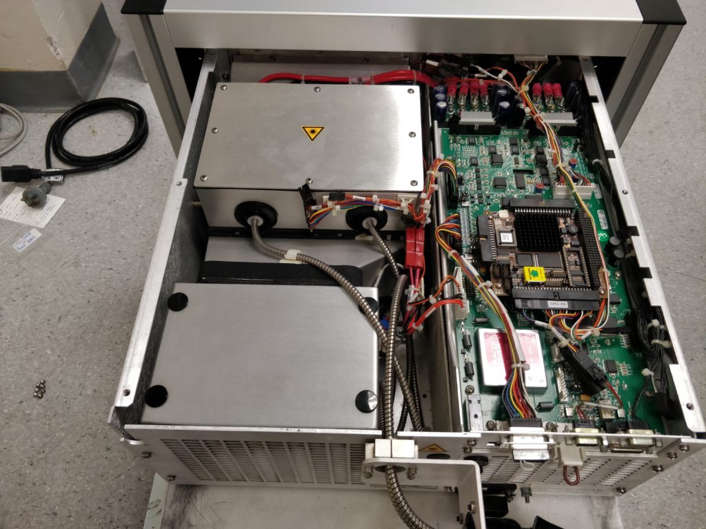
Let’s fast forward through the disassembly and see what it is. This is somewhat awkward and time consuming, but not hard once you know how. (Follow in reverse to see how to do the disassembly.)
That looks a bit scary, but the power supply is out!
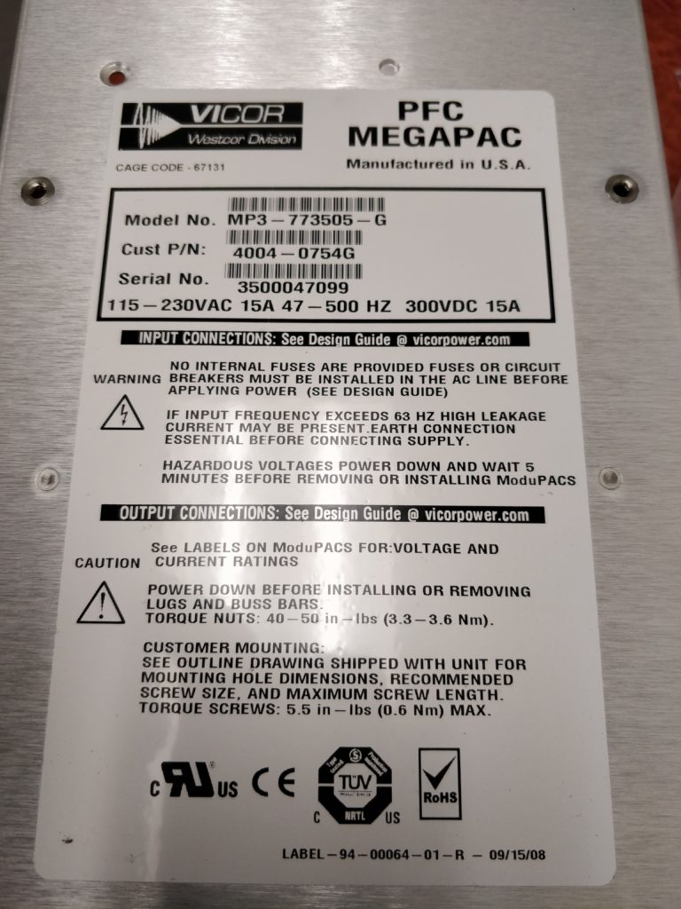
So it’s a commercial unit, a Vicor PFC MegaPAC.
Vicor PFC MegaPAC power supply unit from the Spectra-Physics J80 diode pump laser for the Millennia Prime.
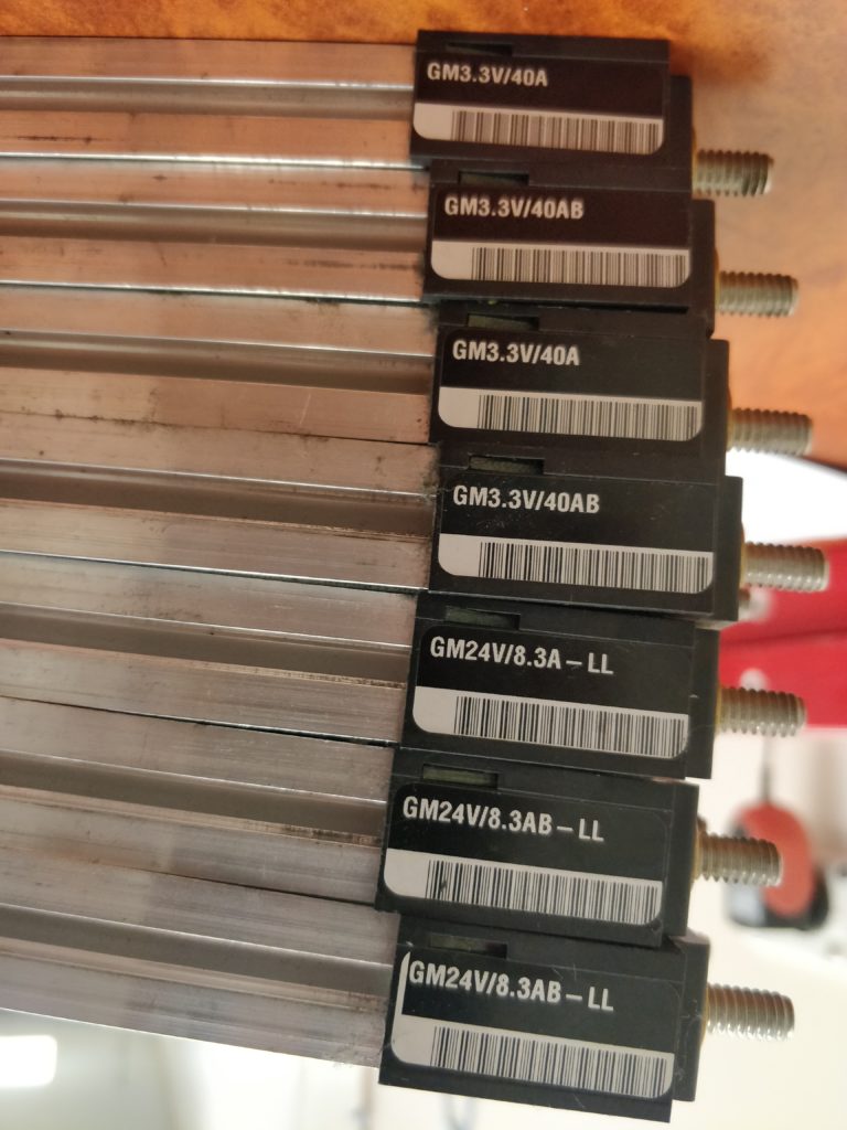
These units are customisable, using a switch mode front-end to produce 300 V DC, which is then converted down to the required voltages using up to 8 DC-DC converter ModuPAC modules. These modules are easily removable.
Vicor ModuPAC modules used in the Spectra-Physics J80 diode pump laser for the Millennia Prime.
The unit is set up to use two high-current 3.3 V rails to run the two laser diodes, and a single 24 V rail to run the thermoelectric cooling system and other electronics. The “B” in the model name indicates they are a “current booster” module, and are connected in parallel to the equivalent non-B module. Note that the J40 system only has a single diode, so I would expect it to only have one 3.3 V rail, and perhaps one fewer of the 24 V boosters.
So the Vicor PFC MegaPAC can be bought new, but they are pretty expensive. We’re looking at over $4000 to replace this unit as configured, with at least a 6-week wait time. The DC-DC converter modules are probably fine though, and can be swapped into another front-end… and there’s a few options on eBay. We ended up getting one shipped from the US for just over $300 (yes, about a third of that was shipping costs). The DC converters swapped over fine and a quick check with a multimeter indicates it’s working OK and no longer tripping the circuit breakers.
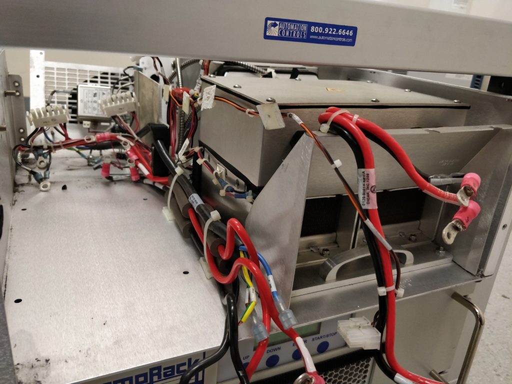
So here’s the reassembly (the disassembly process is just the reverse of this). Bolt the power supply back into the chassis from the side and bottom.
The Vicor PFC MegaPAC is bolted into the J80 frame from the side and underneath.
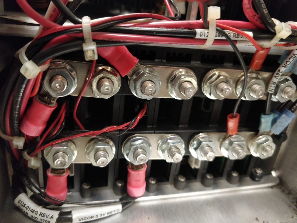
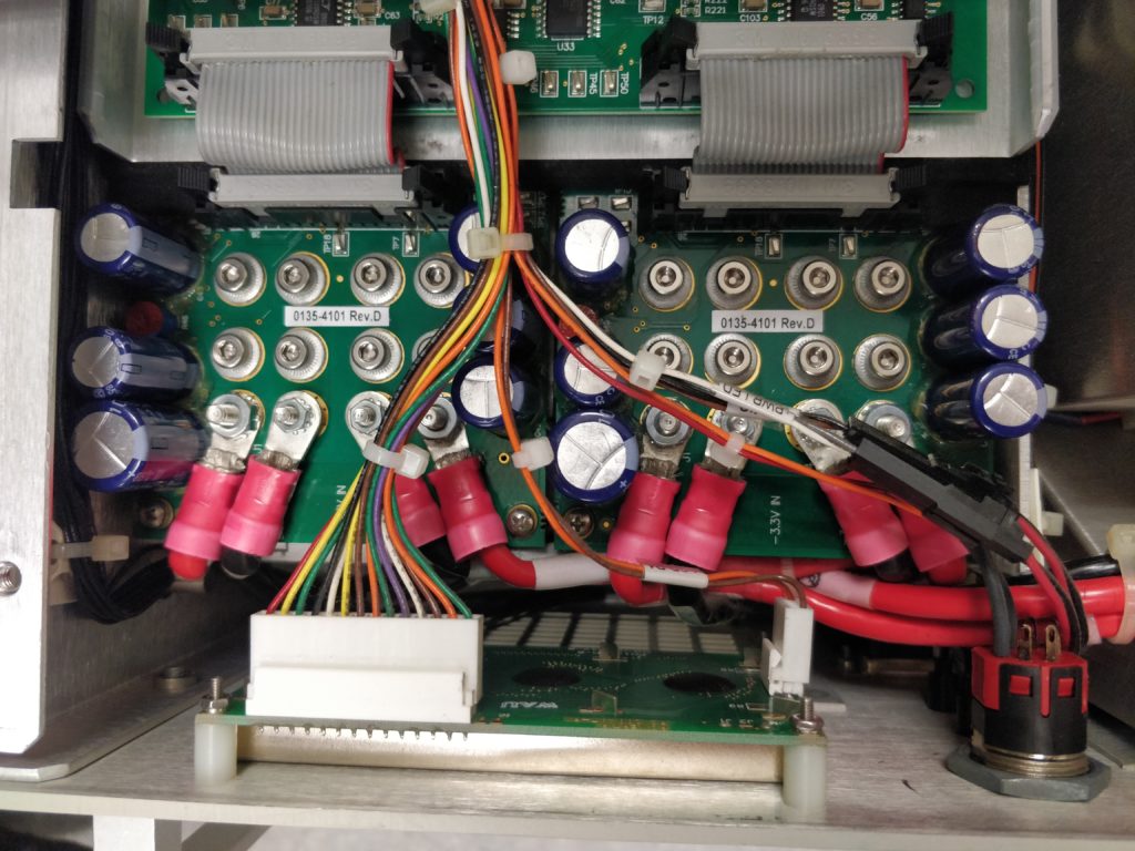
Attach the DC terminals and the voltage trim pot connectors (the small Molex plugs with red and black wires).
DC connections to the Vicor PFC MegaPAC. Two 3.3 V rails and one 24 V rail. The bus bars connect the booster modules to the matching master modules.
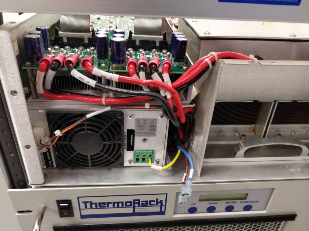
Screw in the mounting bracket for the diode driver circuitry onto the top of the power supply.
Mounting bracket is screwed onto the top of the power supply.
Mount the diode driver circuit boards and plug in the connectors at the back. The black foam is to seal this chamber to direct airflow through the power supply and heatsinks on the diode driver boards. Try not to destroy it during disassembly!
The two diode driver modules of the J80. The J40 would just have one of these.
Connect the high-current 3.3 V lines and diodes to the driver boards. Screw in the ground connection to the power supply, and plug in the connector on the left (this is the connection to the logic board to independently switch the 3.3 V rails on or off).
3.3 V and diode connections to the driver boards.
Fit the rear fan assembly using the nuts on the bottom, then re-attach the back panel. The fibre optic cables are armoured, but be careful here and don’t twist or kink them.
Back panel and fan assembly fitted to the J80.
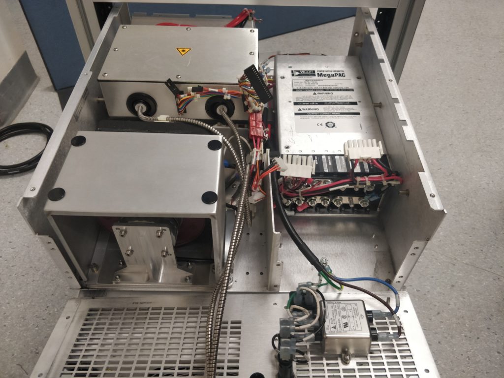
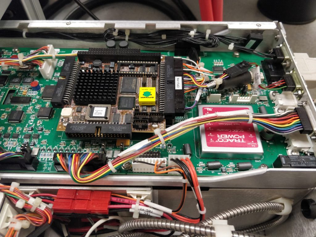
The logic board is then fitted on top of the diode driver boards. Connect the various Molex plugs.
Logic board fitted to the J80.
Note that the rear panel DB-15 connector and the black wires (bottom-right and right side of the above photo, top-right and top of below photo) are actually attached to the front panel. The DB-15 needs to be unscrewed from the rear panel during disassembly.
Logic board fitted to the J80, showing the single-board computer sub-board and 24 V DC-DC power supply module.
As an aside, you can see the single-board computer and 24 V power converter here. That cylinder on the right is a PS/2 keyboard socket. We’ll resist the urge to try hacking it…
Reattach the front panel and connectors to the power switch/power supply, LCD and indicator diodes. The red switch part of the key lock pops out of the lock assembly.
Front panel connections to the J80.
Now put on the top panel, plug it in and fire it up. Yes, it is now working perfectly again!
Here’s my Ph.D thesis, entitled Theoretical and Spectroscopic Studies of Energy and Charge Transport in Organic Semiconductors. It was obtained at the University of Adelaide under the supervision of Tak W. Kee and David M. Huang.
Here’s a family-friendly feature of my music career, Friday’s Fox.
The tracks on the website were recorded and mixed by myself. Thanks to Studio Finetime for the recording space. It was a shame we didn’t get more tracks down….