Delay Calibrations

Update: This post is now outdated! We ended up using a similar, but much improved, spectral interference method using a broadband laser source instead of the continuous-wave HeNe laser. The method is described in the publication on the spectrometer design.

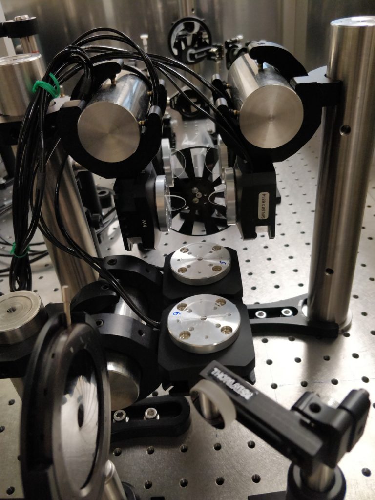
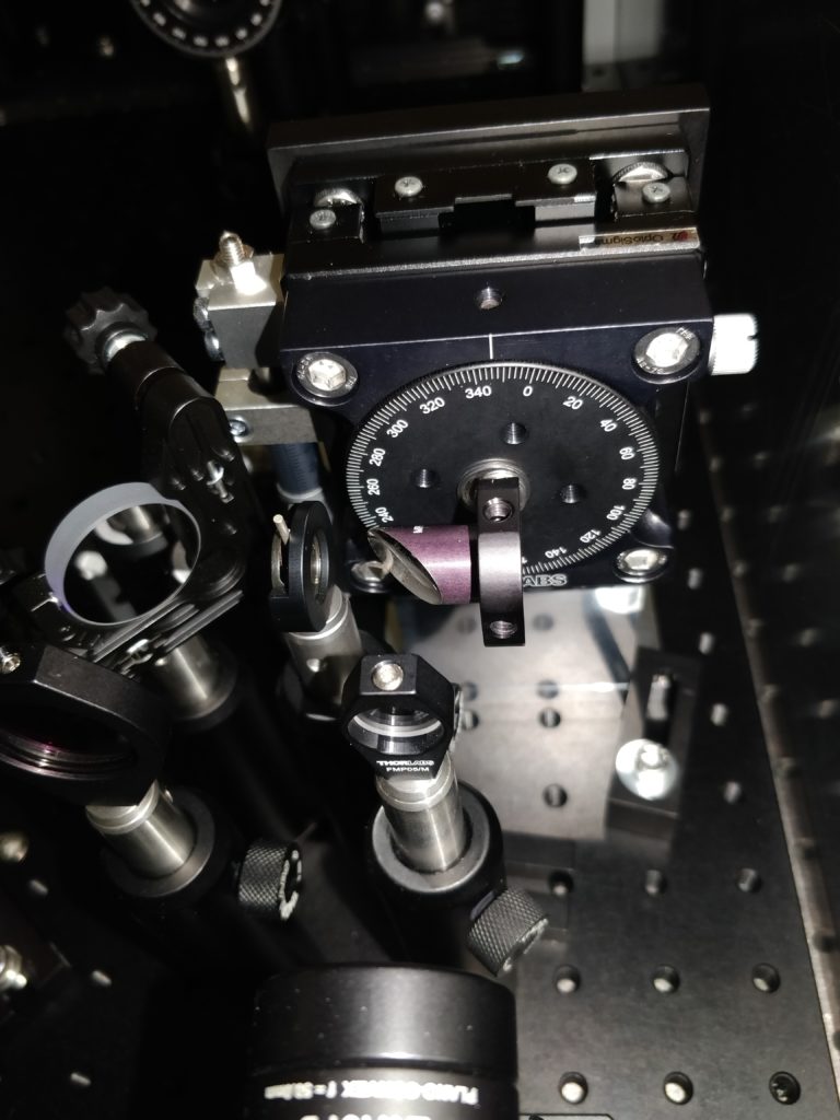
Here is a quick rundown on how the delay stages are calibrated to relate the rotation angle to the delay time of the laser pulse.

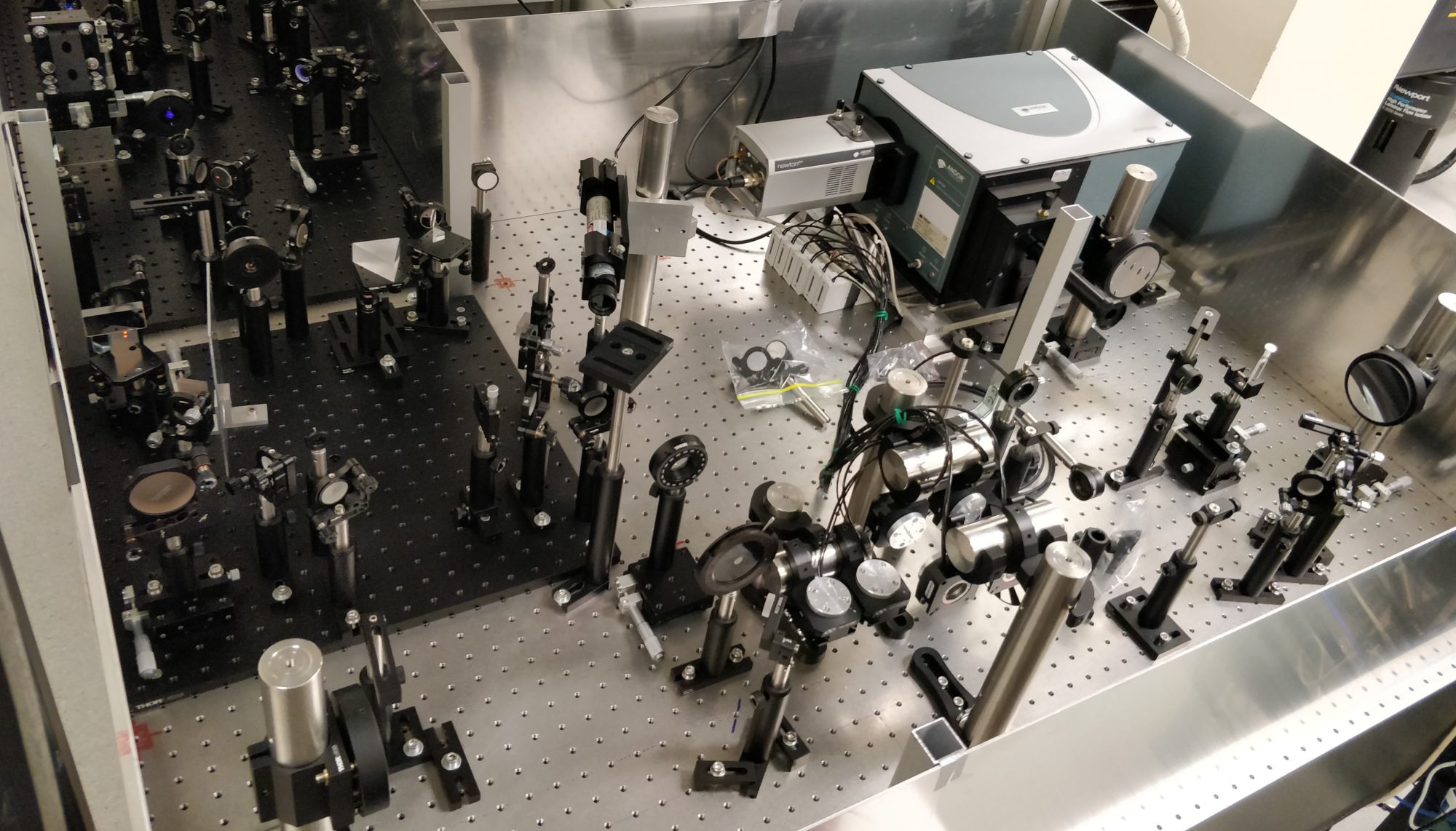
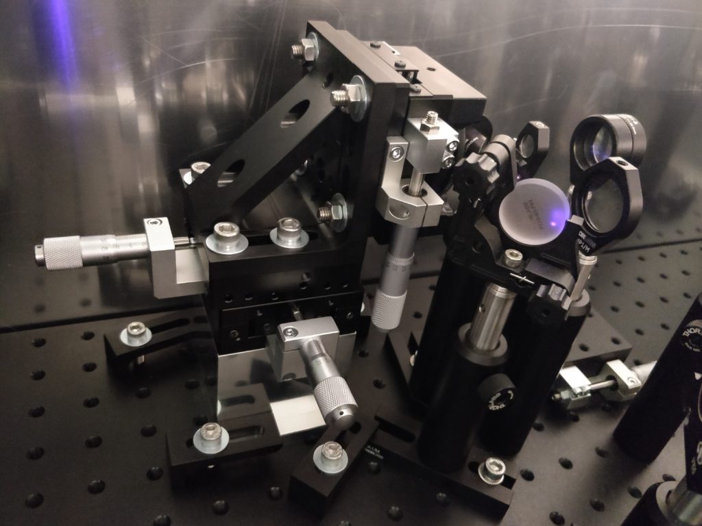
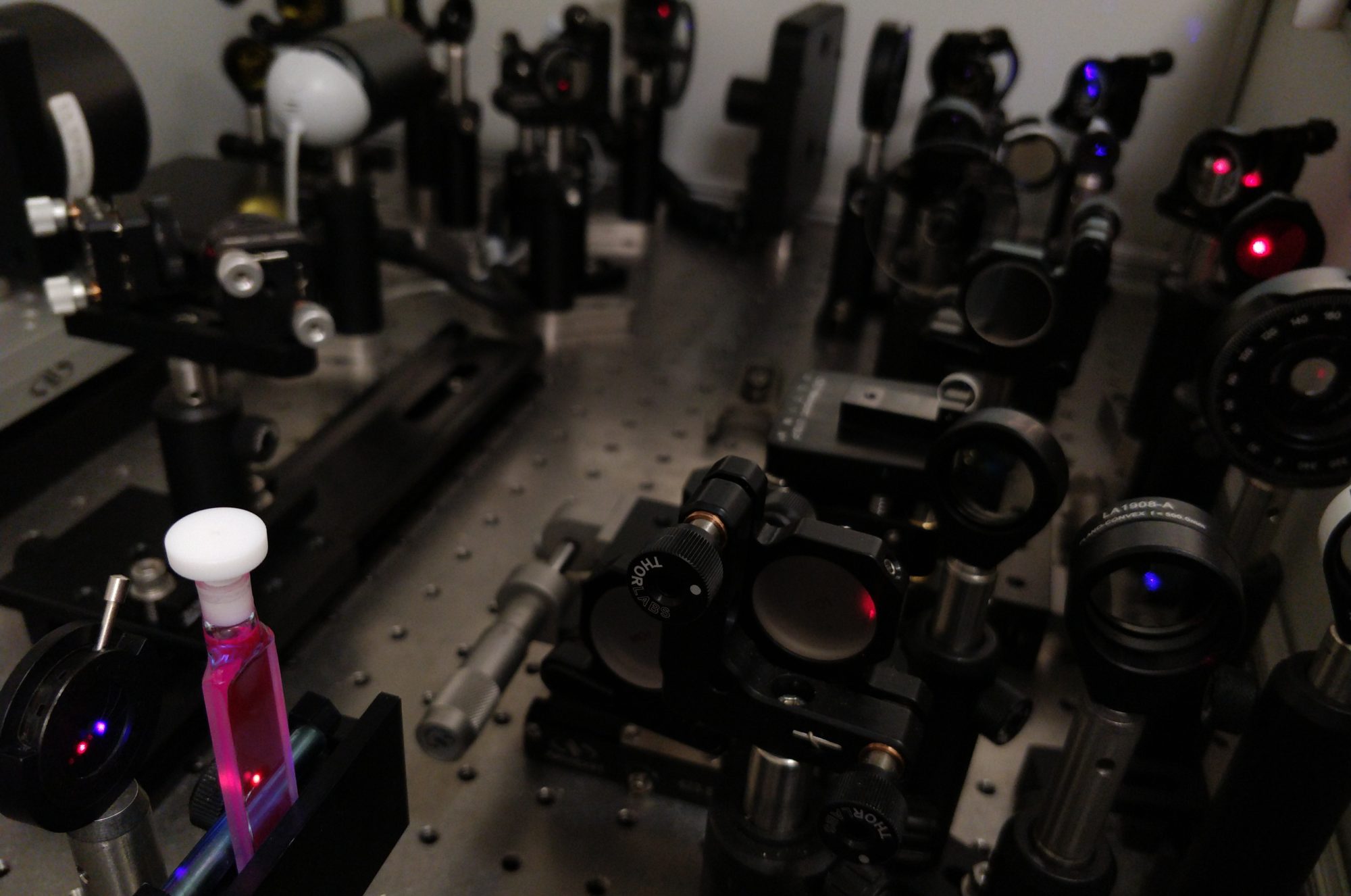
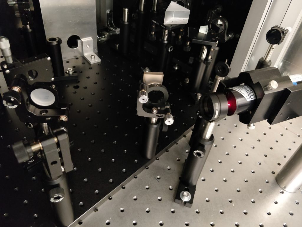
An interferometer is built by inserting a mirror/beamsplitter combination after the delays to interfere pairs of the four beams. A Helium-Neon (HeNe) laser is used as the light source, as the atomic emission at 632.8 nm is very well defined — a requirement to make a nice interference pattern and for use in the calibration fit equation.

Delay Calibration - HeNe Laser
A HeNe laser is used for calibration of the delays.
Delay Calibration - Vertical Pair
Three of four HeNe laser spots used for delay calibration.

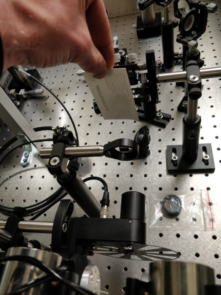
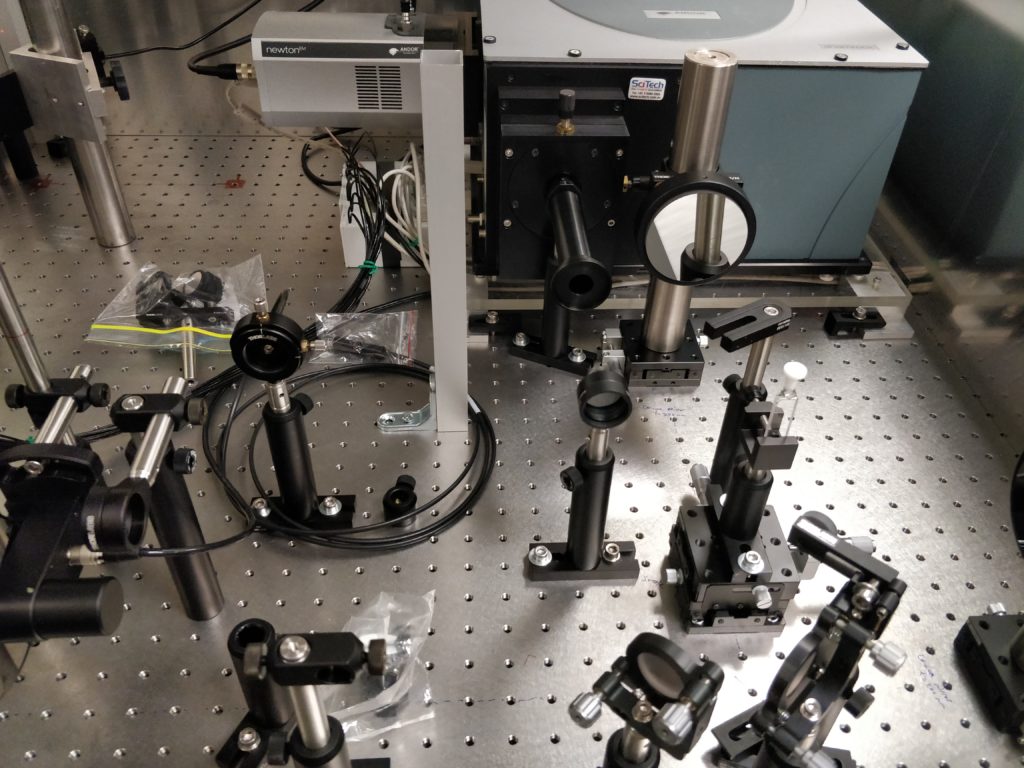
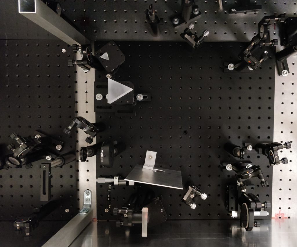
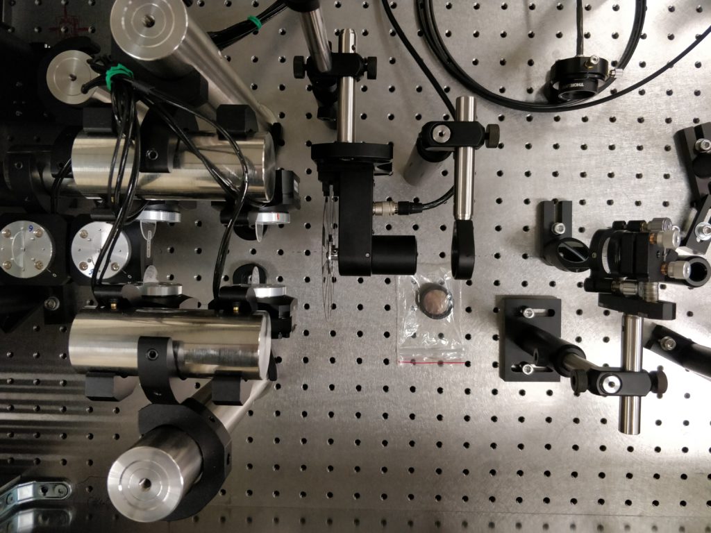
Here we show the vertical configuration of the beamsplitter/mirror combination, which interferes the top and bottom beams, directing them downwards towards the table. The beam is directed to a fibre-optic which feeds the spectrograph and camera.

Overview of back end of interferometer used for delay calibration, in the vertical configuration.

I think this is the first look here at some of the spectrometer software! The intensity at the 632.8 nm laser line is collected as a function of one of the rotational stage angles. The rotational stage is swept between 0° (glass perpendicular to beam) to around 45°.  An interference pattern is generated.

Delay calibration interference pattern and fit.

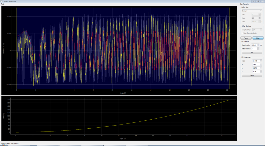
The grey trace is the raw intensity data as a function of rotational stage angle. The yellow trace is with a Savitzky–Golay noise filter applied. The red trace, and the yellow curve in the bottom panel show the theoretical angle-to-delay relationship. As the data is collected, or when the “Fit” button pressed, the fit is performed and the three fitting parameters (α, β, γ) are determined. The fit can also be adjusted in realtime as the parameters are changed manually.

2D spectrometer software - delay calibration
Zoom into part of the collected delay calibration interferogram.

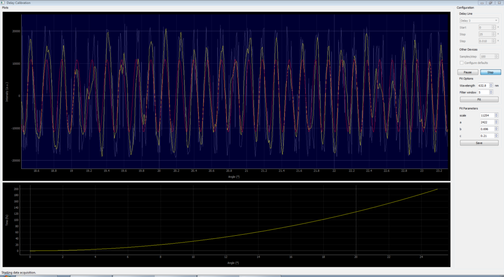
The theoretical model of the glass angle vs delay match the data very well across the entire range of rotation angles. That’s good, as it’s pretty fundamental to the whole spectrometer design!

Spectrograph and Camera

This is the back end of the spectrometer arms. The sample vial is visible, as well as the mirrors and lens used to direct light from the sample into the detector. The spectrograph is an Andor Shamrock, with an Andor Newton CCD camera as the detector. This is able to capture 500 spectra per second.

Spectrograph and Camera
The output end of the spectrometer, showing the sample and the Andor Shamrock spectrograph and Newton camera used as the detector.

2D Spectrometer Delay Stages

These are the three pairs of rotational stages and glass used to control the arrival times of the laser pulse sequence for the 2D spectrometer. The stages are computer controlled, and can rotate with an accuracy of one-thousandth of a degree. By rotating the glass, the effective thickness increases, delaying the laser pulse with control on the attosecond time scale. A pair of glass plates are used for each beam, rotated at opposite angles to correct for the path deviation.

Delay stages
The input side of the spectrometer, showing the three pairs of rotational stages and glass used to control the relative arrival times of the laser pulse sequence.

Pulse Compressor

Here’s the layout of the pulse compressor. It consists of both grating and prism stages.

Pulse compressor
Two stage pulse compressor, using diffraction grating and prism sections. The laser pulses from the NOPA output are highly chirped with a duration of 400 fs or more. This compensates for the chirp, producing pulses of 20 fs or less.

Non-colinear Optical Parametric Amplifier (NOPA)

Here’s the layout of the non-colinear optical parametric amplifier (NOPA). It’s a tunable light source which can produce laser light anywhere across the visible spectrum. It’s fed by the output of our titanium-sapphire regenerative amplifier (Spitfire, Spectra Physics), which provides 100 fs duration pulses with a 1 kHz repetition rate, centred at a wavelength of 800 nm. We split that to produce a white-light continuum seed and a 400 nm pump beam. The precise angle and timing of the overlap of these beams on the nonlinear crystal (beta barium borate, BBO) will change the wavelength of the NOPA output. Currently this is generating light centred around 600 nm.

Non-colinear optical parametric amplifier (NOPA)
Non-colinear optical parametric amplifier (NOPA). A tunable light source which can produce laser light anywhere across the visible range.

The output is strongly affected by the quality of the white-light seed. The white light is produced by focusing a small amount of the 800 nm laser onto a pure sapphire crystal. The produced white light radiates out and needs to be collected and collimated using a precisely placed curved mirror.

NOPA white light
Sapphire plate and off-axis parabolic mirror used to generate and collimate the white-light continuum.

NOPA White Light
Mounting for the off-axis parabolic mirror used to provide precise 4-axis positioning.